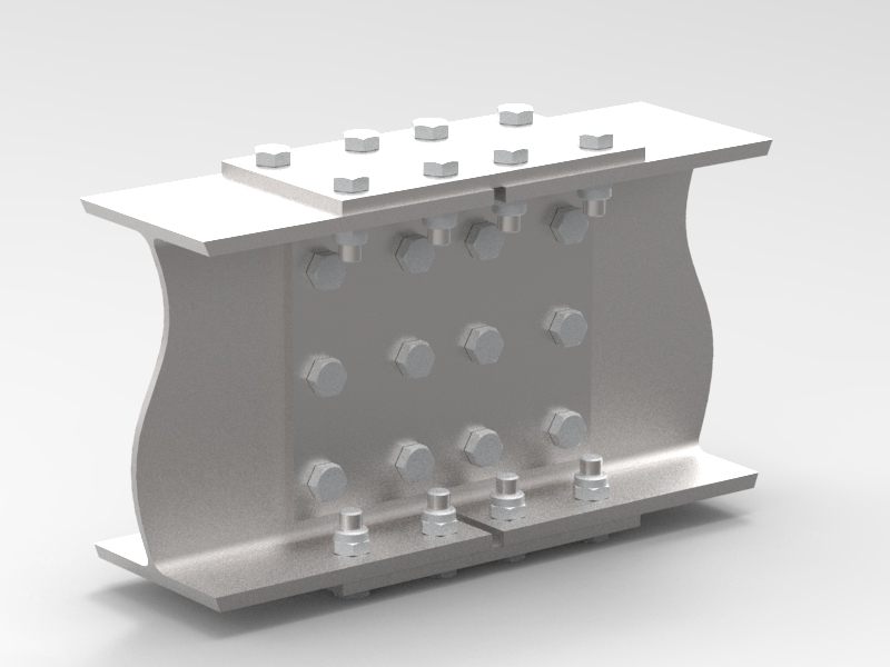
2.3 Eccentric Loading applied out of plane to the bolt group
This type of loading occurs when external forces act in plane to the faying surfaces and gives rise to shear through the bolt shank or threaded cross section. As with direct tension loading the external applied force is shared evenly over the total number of bolts in the group.
Sometimes bolt patterns are unavoidably arbitrary and taking moments to resolve bolt forces becomes impractical. Two methods are employed by various steel construction institutions around the world. These are the Elastic method, which assumes a triangular distribution of bolt forces [aw. cit.] and the Plastic Method which assumes that each row of bolts achieves its full design strength. The latter method relies on the ductility of the joint components and is more complex to use for the none structural engineer. Subsequently, it is beyond the scope of this article but if the reader is interested, further explanation is given in reference [aw. cit.].
2.3.1 Elastic Method
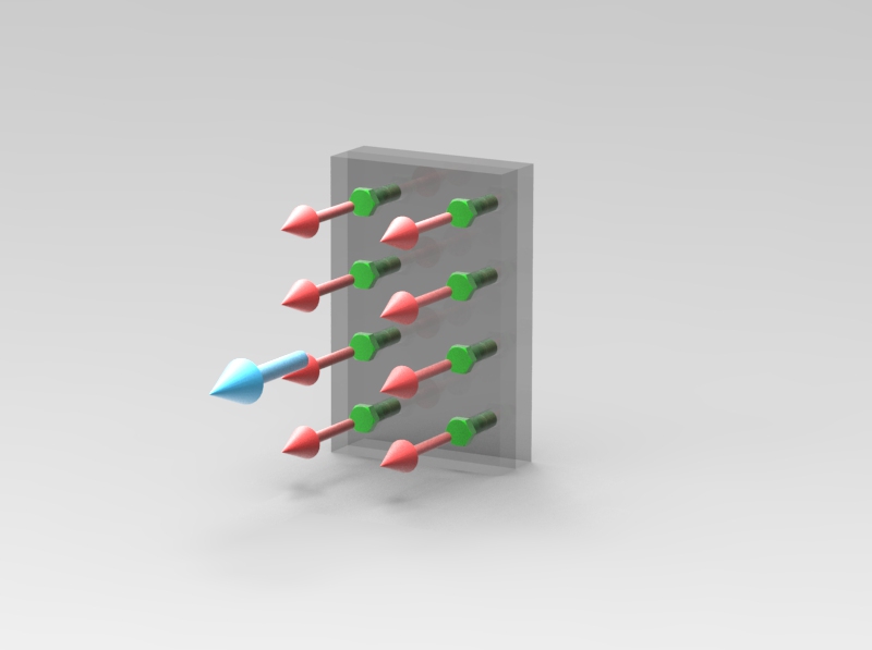
In the UK it is common practice to assume a triangular distribution of bolt forces which are all in tension. They react against a compression zone which sits somewhere near the lower bolts in the joint. It is common practice when designing beam to column connections in buildings to assume the compression zone is in line with the compression flange of the beam [aw. cit.].
In this article, we will assume the centroid or neutral axis of the bolt group lays in the centre of the group, contrary to the above. This implies that there are as many bolts in tension as there are in compression. This can be shown to be a conservative assumption as the bolt which experiences the greatest tension is further away from the compression zone than the centre of the joint. As the resistance to an applied moment is defined by the bolt group moment of inertia, the further the bolt is away from the neutral axis then the greater its contribution to the inertia value by the square relationship to distance.
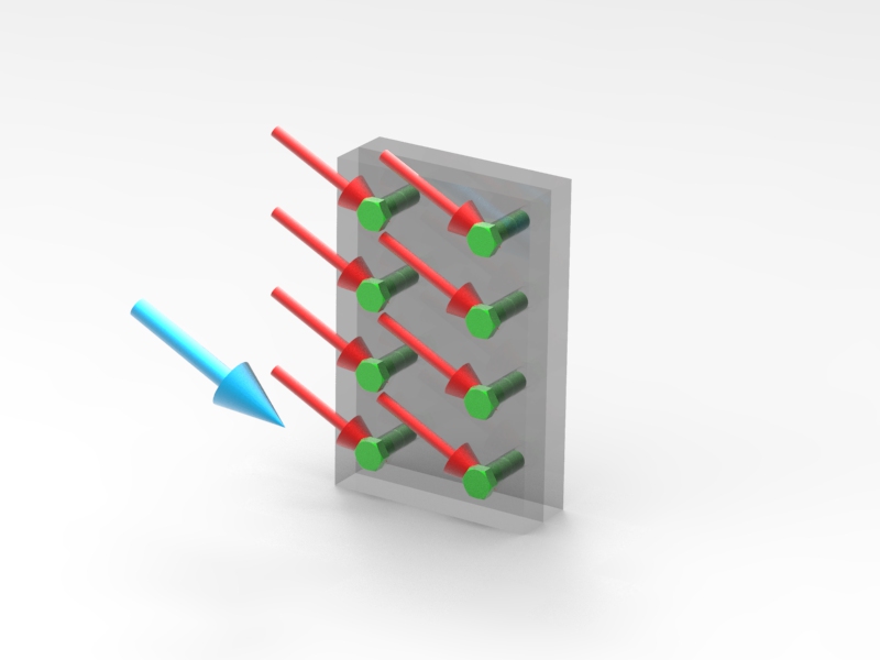
Using this assumption, it can be shown that a bolted joint behaves in a similar manner to a beam in bending or a shaft in torsion when external moments are applied. Just as with a beam or shaft the bolts furthest from the centroid or neutral axis of the joint experience the largest force when a moment is applied. If we extend this analogy and postulate that the beam bending and shaft torsion formulas can be rewritten to give bolt forces then the following expressions are derived :-
\(M/I = \sigma/y - Eq. 2.3.1.0\)
Which rearranges to :-
\(\sigma = My/I - Eq. 2.3.1.1\)
Where :-
\(M\) = Externally applied moment
\(I\) = Second Moment of Area
\(\sigma\) = Bending Stress
\(y\) = Vertical distance from neutral axis
However, we are interested in finding the force at each bolt which is analogous to finding the force at a given distance from the neutral axis of a beam in bending. As Stress is defined as force per unit area, equation 2.3.1.1 can be expressed in terms of F or Force as:-
\(F = MAy/I - Eq. 2.3.1.2\)
Where :-
\(F\) = Force at bolt position y from the neutral axis
\(A\) = Bolt cross-sectional area
As the moment and bolt position values are prescribed at the design stage we need to find the bolt group moment of inertia, I to enable us to analytically determine the applied force at each bolt. If we assume that the bolt group moment of Inertia is analogous to the 2nd moment of area used in beam bending theory then we should be able to use the parallel axis theorem, which is expressed for beam bending as:-
\(I_{xx} = I_{gg} + Ay^2 - Eq. 2.3.1.3\) [aw. cit.]
Where :-
\(I_{xx}\) = Second moment of area taken about bolt group neutral axis
\(I_{gg}\) = Second moment of area taken about one bolt cross sectional area neutral axis
We can think of the bolt group moment of inertia as a quantity that defines how a set of points or infinitesimally small areas resist an applied moment. These points are coincident to the centre of the bolt positions. The more points (or bolts) that are scattered further away from the neutral axis, the larger the moment of inertia value and the more resistance the bolted joint gives to the applied moment. Hence, the larger the inertia the lower the forces are at each bolt in the joint. If we draw parallels to a beam, the material is concentrated in the flange area of a beam which is the furthest away from the neutral axis. This gives the greatest 2nd moment of area and subsequently greatest resistance to bending.
We can generate an expression for the bolt group moment of inertia by assuming the radius of this small area approaches 0 and all the bolts are of the same nominal size. See the derivation below :-
The second moment of area of any circle is defined by :-
\(\pi r^4/4 - Eq. 2.3.1.4\)
Equation 2.3.1.3 can now be rewritten as:-
\(I_{xx} = A(r^2/4 + y^2) - Eq. 2.3.1.5\)
If we let r tend to 0 as we are considering a point, then the \(r^2/4\) term can be removed from the expression above and thus can be rewritten as:-
\(I_{xx} = Ay^2 - Eq. 2.3.1.6\)
This expression only considers one remote point from the neutral axis. The total moment of inertia for the bolt group is the sum of all \(Ay^2\) terms or:-
\(A\displaystyle\sum_{i=1}^n y_i^2 - Eq. 2.3.1.7\)
If we substitute equation 2.3.1.7 into 2.3.1.2 then we get:-
\(F = My/\displaystyle\sum_{i=1}^n y_i^2 - Eq. 2.3.1.8\)
Now the bolt area A is no longer part of the expression for bolt force.
Up to now we have only considered a uniaxial state of bending, however a bolted joint can experience bending about two axes. An expression can be derived for a state of multiaxial bending based upon the above theory and as we have assumed the principle of linear superpositioning then we can simply sum the two values to achieve a total force. See below :-
\(F_{Combined} = M_x x/\displaystyle\sum_{i=1}^n x_{i}^2 + M_y y/\displaystyle\sum_{i=1}^n y_{i}^2 - Eq. 2.3.1.9\)
The designer would need to evaluate expression 2.3.1.9 for all bolt instances to determine the largest bolt force produced by multiaxial bending. As mentioned previously this can be added to forces produced by other types of loading to obtain a total maximum bolt force.
If the position of the neutral axis is not obvious by inspection, which is usually the case for an arbitrary set of points, then the position can be calculated from a given datum. The position is found by taking moments about the datum line. The following expression can be used to find the distance to the neutral axis from a given datum.
\(X_{na} = \displaystyle\sum_{i=1}^n (x_{i}-x_{datum})/n - Eq. 2.3.1.10\)
\(Y_{na} = \displaystyle\sum_{i=1}^n (y_{i}-y_{datum})/n - Eq. 2.3.1.11\)
Where:-
\(n\) = Number of bolts
\(x_{datum}\) = Arbitary datum position to measure all x bolt positions from.
\(y_{datum}\) = Arbitary datum position to measure all y bolt positions from.